




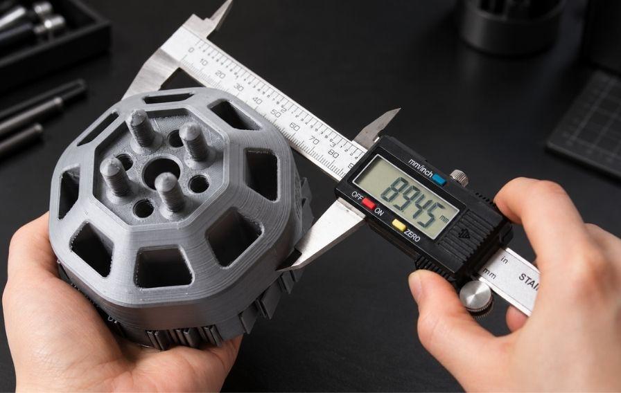
Anyone moving from printing models to printing parts that have to fit together runs into the same question. How close will the printed dimension be to the one you drew? That question is what 3D printing tolerances are about, and the honest answer is that it depends on the technology, the material, the machine, and the part itself. Get a feel for the numbers and you can design parts that fit first time instead of reprinting them twice.
This article sets out what tolerance actually means, what pushes it around, and the accuracy you can reasonably expect from FFF, SLA, and SLS. It finishes with practical design and finishing steps that tighten the fit of the parts you print.
What do we mean by 3D printing tolerances?
Four related terms get muddled, so it helps to separate them. Tolerance is the deviation you allow from a nominal dimension, written as something like ±0.2mm. Accuracy is how close a printed dimension lands to the intended one. Precision, or repeatability, is how consistent the result is from one print to the next. Resolution is the smallest feature or layer the machine can form, which is not the same as accuracy at all.
The distinction matters. A printer can have fine resolution and still be inaccurate if it is poorly calibrated, and it can be accurate on average yet inconsistent run to run. When people talk about 3D printing tolerances, they usually mean the combination of accuracy and repeatability you can count on for a given process. That is the figure you design around.
What affects 3D printing tolerances?
No single number describes a process, because several factors stack up on every print:
- Material behaviour. Plastics shrink as they cool, and different materials shrink by different amounts. ABS and nylon move more than PLA, which makes them harder to hold to size.
- Part size. Deviation tends to grow with length, so a 200mm part drifts further from nominal than a 20mm one, even on the same machine.
- Geometry. Thin walls, tall thin features, large flat areas, and sharp overhangs all distort more than compact, well-supported shapes.
- Orientation. The same part printed flat or upright can measure differently, because layer lines and support contact fall in different places.
- Calibration. Flow rate, temperature, bed levelling, and belt tension all shift dimensions if they drift out of tune.
- Ambient conditions. Draughts and temperature swings warp large parts, especially in materials that shrink, so an enclosure holds dimensions steadier.
- Post-processing. Sanding, support removal, and heat all change final dimensions, sometimes helpfully and sometimes not.
Because these stack, the 3D printing tolerances you achieve in practice depend as much on your setup and your part as on the badge on the machine.
Add Your Heading Text Here
Here is the part most people come for: the accuracy you can expect from each process. Treat these as typical, well-tuned figures rather than guarantees, since calibration and geometry move them either way.
FFF
FFF (Fused Filament Fabrication) is the most common desktop process and the most variable on tolerance. A well-set-up machine typically holds around ±0.5% of the dimension, with a lower limit near ±0.5mm on desktop hardware. On small, well-calibrated parts you can do better, often ±0.2 to ±0.3mm. Holes tend to print slightly undersized, and the layer (Z) direction is usually less accurate than the flat X and Y plane. Machines from Bambu Lab 3D printers hold tighter tolerances than older open-frame printers, thanks to stiffer frames and better calibration routines.
Watch the first few layers too. A squashed first layer, sometimes called elephant’s foot, widens the base of a part and can throw off a fit near the bottom edge. A small chamfer on the base or a tuned first-layer height keeps it in check.
Consistent input helps as well. Filament that varies in diameter changes how much material the printer extrudes, which shows up as dimensional drift. Good 3D printing filament is held to a tight diameter tolerance, often around 1.75mm ±0.02mm, so the flow stays predictable across a print.
SLA
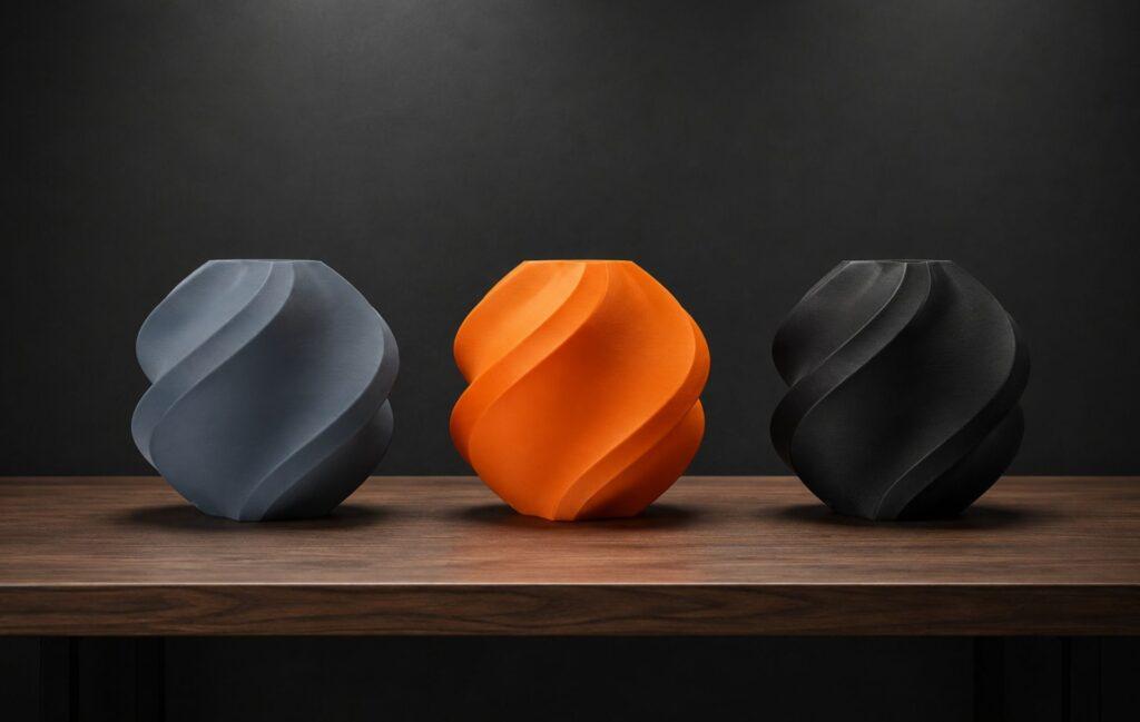
SLA (Stereolithography) cures liquid resin with light and gives the finest detail and the tightest tolerances of the common desktop processes. Typical accuracy sits around ±0.2% with a lower limit near ±0.1 to ±0.2mm on well-controlled parts. The catch is that resin parts can distort if they are under-cured, over-cured, or left unsupported in the green state, so handling and curing discipline matter. For small precise parts, Formlabs 3D printers resin machines are a common choice where fit is critical.
SLS
SLS (Selective Laser Sintering) fuses nylon powder and typically holds ±0.5% with a lower limit of ±0.3mm, whichever is larger, so its floor on small parts sits between the other two processes. It needs no supports, which removes one source of distortion, but the heated powder bed introduces its own shrinkage that has to be compensated in the machine profile. That profile corrects for a few per cent of shrinkage across the bed, which is why a well-maintained profile matters as much as the hardware. For functional nylon parts produced in batches, SLS gives dependable, repeatable results across a full build.
How accuracy is quoted, and why ±0.2mm isn't the whole story
A single tolerance figure hides an important detail. Most processes are quoted as a base value plus a percentage of the dimension, such as ±0.2mm or ±0.2%, whichever is larger. That means a small part is governed by the fixed base figure, while a large part is governed by the percentage. A ±0.3% process holds a 20mm feature to about ±0.3mm at worst, but the same process on a 200mm feature could drift by ±0.6mm.
Direction matters too. Most printed parts are anisotropic, meaning they behave differently along different axes. The flat X and Y plane is usually more accurate than the Z height, and strength follows a similar pattern. When a fit is critical, note which axis carries the important dimension and orient the part so that dimension sits in the printer’s stronger plane.
How do you check the tolerances you're getting?
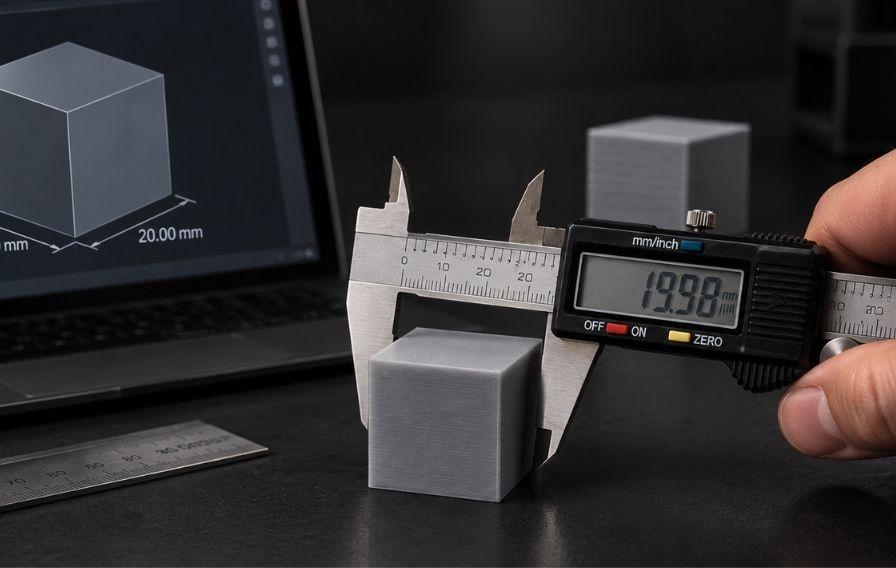
You cannot design around a number you have not measured. A set of digital callipers reading to 0.01mm is enough to check most desktop work, and it quickly shows how your machine and material actually behave.
- Print a simple test block with known nominal dimensions, then measure each axis and compare to the CAD (Computer-Aided Design) figure.
- Note the direction of the error. If holes come out small or outer dimensions come out large, that points to flow or first-layer squish rather than random noise.
- Apply a correction. Small, consistent errors can be dialled out with flow calibration or a scale compensation in the slicer, so the machine prints closer to nominal.
- Check the first part of every batch. A quick first-article measurement against the drawing catches a drifting machine before it spoils a whole run.
Measuring your own parts beats any datasheet, because it captures your exact machine, material, and settings rather than an ideal case. If repeatability is the worry, print the same test three times and compare. Tight agreement between them means you can trust the process, while noticeable scatter points to a mechanical or thermal issue worth fixing before it reaches a real part.
Designing for 3D printing tolerances
You can design a lot of tolerance trouble out of a part before it reaches the printer. A few habits cover most cases:
- Add clearance to mating parts. For FFF sliding or assembly fits, start with 0.2 to 0.5mm of gap and adjust from a test print. Resin needs less, and SLS sits in between.
- Oversize holes or finish them afterward. Holes print undersized on most processes, so add a little diameter or drill and ream critical bores to size.
- Avoid printed threads for anything load-bearing. Tap the hole after printing, or fit a heat-set insert, rather than relying on a fine printed thread.
- Print a test coupon first. A small calibration or tolerance print in your chosen material tells you the real gap you need far more reliably than a spec sheet.
As a worked example, say a lid needs to slide onto a box wall that is 40mm across. On an FFF machine holding roughly ±0.3mm on parts that size, drawing the lid opening at exactly 40mm risks a tight or impossible fit. Opening it to 40.4mm gives a gap that slides without rattling, and a single test print tells you whether to nudge it tighter or looser. Designing around realistic 3D printing tolerances, rather than the ideal figure on a datasheet, is the difference between a part that assembles and one that binds.
Hitting tighter tolerances with post-processing
When a part needs to be tighter than the process delivers, finish the critical features rather than chasing the printer. Reaming a printed hole to a drill size, facing a mating surface flat, or lightly sanding a boss gives you a machined tolerance on the features that matter, while the rest of the part stays as printed. For metal AM (Additive Manufacturing) parts, machining critical faces after printing is standard practice, because the as-printed surface rarely meets a tight fit on its own.
The point is to spend effort only where it counts. Most of a part can sit at printed tolerance while two or three features get finished to size. For strong functional parts that need to hold their dimensions under load, composite machines such as Markforged hold shape well, and a light finishing pass handles the few surfaces that must be exact.
When a part has to be right first time
Some parts leave no room for trial and error, such as a jig that positions an expensive workpiece, a housing that has to seal, or a mount that locates a sensor. For those, match the process to the requirement rather than forcing your usual machine to cover every job. SLA suits fine, precise detail. SLS gives repeatable functional batches. FFF with a finishing pass handles larger or lower-cost parts where a little hand-work is acceptable.
It also pays to separate the critical dimensions from the rest early in the design. Mark the two or three features that must hold size, decide how you will achieve them, whether by process choice, orientation, or post-machining, and let the remaining features sit at standard printed tolerance. That keeps cost and effort proportional to what the part actually needs.
If you do not own the right process, or the part is a one-off where buying a machine makes no sense, a print service fills the gap. The Digital Parts Factory can produce a tolerance-critical part in the process that suits it and finish the features that must be exact, which is often cheaper than reprinting a difficult part again and again on the wrong machine.
Final thoughts
The accuracy you get is never a single number. Realistic 3D printing tolerances depend on the process, the material, the size and shape of the part, and how well the machine is tuned. As a rough guide, expect the tightest results from SLA, dependable mid-range accuracy from SLS, and the widest spread from FFF, with a well-calibrated desktop machine closing much of that gap on small parts.
Design with sensible clearances, print a test coupon before a full run, and finish only the features that must be exact. That approach gets parts fitting first time far more often than trusting a datasheet figure. If you are choosing a machine around a specific accuracy target, our team in Ripon can print your part in more than one process so you can measure the fit yourself.